


Wire selection and ratings, an introduction
If repairing an existing harness or working from prints, the wire size can be easily determined or found on the drawing, and would have been engineered to ensure the wiring harness provides safe and reliable operation. When it comes to wire selection, the current rating, or ampacity as it's also referred to as, is an important part of the process, but not the only one. The wire size you'll see listed (if at all) is dependent on a number of variables, which need to be evaluated to ensure the wiring is correct for your particular application. In this article we go into what these variables are, factors to take into consideration, types of wire, and a couple time tested wire selection methods.
1. Wire Ratings
- Current rating (ampacity) - The maximum continuous current that can be applied to a wire under specified operating conditions, and not result in a temperature rise that exceeds the temperature rating of the wire. Some wire manufacturers may list a current rating, but without knowing the variables used to determine that rating, the wire may or may not be suitable to your application.
- Temperature rating - The temperature range a wire can be operated in without damage to the insulation. Typically a measure of the insulation's ability to withstand the combination of ambient temperature and current related conductor temperature rise [2, par. 11-77].
- Voltage rating - The maximum continuous voltage that can be applied to a wire before insulation breakdown, permitting leakage into adjacent circuits or the chassis.
- Wire size - The size of the wire conductor in either: Cross sectional area (mm2), or American Wire Gauge (AWG). Note though listed sizes are an approximation rounded to the nearest commonly referenced wire size due to the cross-sectional variance of stranded wire vs. solid wire that the AWG standard is based on, and variance between styles of stranded wire of the same size. Therefore the calculated size will be slightly greater or smaller than the listed wire size.
2. Variables
In general, wires must be sized so that they: have sufficient mechanical strength to allow for service conditions; do not exceed allowable voltage drop levels; are protected by system circuit protection devices; and meet circuit current carrying requirements [2, par. 11-66]. Below is a non-inclusive list of variables to consider.
- Ambient Temperature - Temperature within an engine bay can be effectively managed with airflow at speed, but what do those temps climb to during a pitstop, or back in the paddock after a stint?
- Temperature Rise - On top of the ambient temperature, the temperature rise related to circuit current needs to be within the temperature rating of the wire.
- Voltage Drop - The wire size needs to be large enough to not only meet the required current carrying capacity, but also the allowable voltage drop.
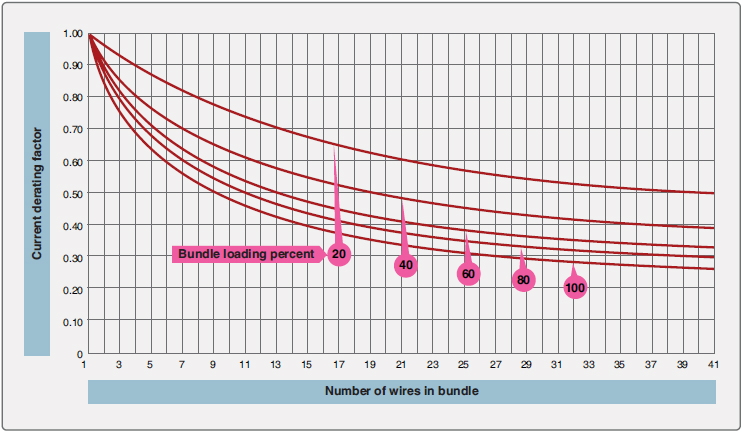
- Number of Conductors - Most calculations are based on a single wire in free air. When wires are bundled into a harness, the current derived for a single wire must be reduced [2, par. 11-67].
- Connector Terminals - In some instances, the wire may be capable of carrying more current than is recommended for the contacts of the related connector. In this instance, it is the contact rating that dictates the maximum current to be carried by a wire [2, par. 11-67].
- Chemical Resistance - Is the wire affected by fuel, brake fluid? Wire that meets a test standard is tested only to a specific list of fluids, with a defined duration and temperature parameters. How representative are these parameters to your application?
- Handling - If it is desirable to use wire sizes smaller than 20 AWG, particular attention should be given to the mechanical strength and installation handling of these wires, e.g. vibration, flexing, and termination. As a general practice, wires smaller than size 20 AWG should be provided with additional support and be grouped with at least three other wires [2, par. 11-66].
- Adjacent Materials - While some wires have a temperature rating of 260°C, connectors with a plastic housing usually have a much lower temperature rating, at most, 125°C.
- Mechanical Performance - Abrasion resistance, and cut-through resistance varies with the insulation material as well. Will there be relative motion between wires in a bundle? Will wires cross over each other? How are the wires supported from adjacent structure or feed through holes?
- Flame Resistance - All wire can burn, the degree to which it sustains combustion or self-extinguishes varies with insulation material.
3. Types of Wire
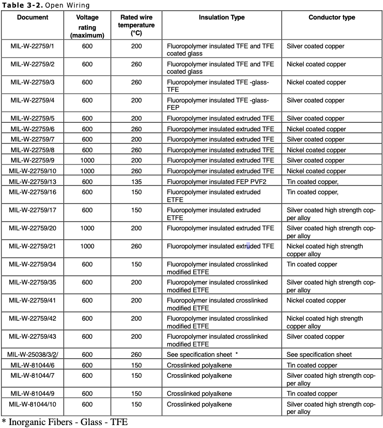
There are many different specifications of wire available, from Mil-Spec (MS, now AS), to OEM, to commercial grades. For content length, this article will focus on the Mil-Spec types used for power and signal wires due to its common use in motorsports and high performance applications. This is not to discourage the use of automotive wire, such as TXL, GXL, or SXL, as these are also used very effectively in motorsports. There are two main categories of wires, suitable for either "open wiring" or "protected wiring" applications.
- Open Wiring - Used in point to point open harnesses without special enclosing means, where each wire provides enough insulation to resist damage from handling and service exposure, and offers the advantages of ease of maintenance and reduced weight [2, par. 11-86]. Most commonly MIL-W-22759/16. For full list see Table 3-2 below.
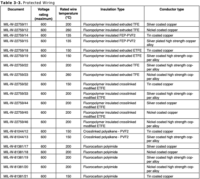
- Protected Wiring - Used within equipment boxes, or has additional protection, such as an exterior jacket, conduit, tray, or other covering [2, par. 11-87]. Most commonly MIL-W-22759/32 or Raychem SPEC 55 wire. For full list see Table 3-3 below.
Whether it's open or protected wiring, it will always be stranded rather than solid to minimize fatigue breakage, and always at least tin plated. Bare copper develops a surface oxide coating at a rate dependent on temperature. This oxide film is a poor conductor of electricity and inhibits re-termination of wire. Therefore, all wiring has a coating of either tin, silver, or nickel, that have far slower oxidation rates [2, par. 11-77].
- Tin coated - Used where temperature rating does not exceed 150°C.
- Silver coated - Used where temperature rating does not exceed 200°C.
- Nickel coated - Used where temperature rating does not exceed 260°C, however most wire using such a coating have insulation that cannot exceed that temperature on long-term exposure. Soldered terminations require the use of different solder sleeves or flux than those of tin or silver-plated conductor [2, par. 11-77].
- PI-Aromatic polyamide / Kapton - AS81381. Note: PI insulation as a sole insulator is avoided in aerospace applications these days due to flashover and arc tracking [11]. However, hybrid construction techniques utilizing PI and other materials have produced successful insulation materials that continue to be used today in new designs. Hybrid insulation is classified as composite.
- Composite - AS22759/80 thru /92 and /180 thru /192. A hybrid insulation utilizing layers of PI (Kapton) and fluoropolymer (TFE) in its construction.
- ETFE / Tefzel - Extruded ethylenetetrafluoroethylene. Maximum temperature rating of 150°C.
- PTFE / Teflon - Extruded polytetrafluoroethylene. Maximum temperature rating of 260°C.
- XLETFE - Crosslinked ETFE. A process of radiation cross-linking the polymer chains is used to thermally set the plastic. This prevents the material from softening and melting at elevated temperature [2, App. 1 pg. 9]. Maximum temperature rating of 200°C.
| Most desirable -> Least | |||||
|---|---|---|---|---|---|
| Relative Ranking | 1 | 2 | 3 | 4 | 5 |
| Cost | ETFE | XLETFE | PTFE | PI | COMP |
| Space | PI | XLETFE | ETFE | COMP | PTFE |
| Weight | PI | XLETFE | ETFE | COMP | PTFE |
| Temperature | PTFE | COMP | PI | XLETFE | ETFE |
| Abrasion resistance | PI | XLETFE | ETFE | COMP | PTFE |
| Cut-through resistance | PI | COMP | XLETFE | ETFE | PTFE |
| Flammability | PTFE | COMP | PI | ETFE | XLETFE |
| Smoke generation | PI | COMP | PTFE | ETFE | XLETFE |
| Flexibility | PTFE | ETFE | COMP | XLETFE | PI |
| Arc propagation resistance | PTFE | ETFE | COMP | XLETFE | PI |
4. Wire Selection Methods
Wire selection can be a time consuming process, but is necessary to achieve the desired results for reliability, safety, and prevent failure in the particular application. Current guidance relies on the use of published and publicly available standards, not limited to the following:
- AS50881 - Aerospace Vehicle Wiring, from the Society of Automotive Engineers (SAE) Available for purchase from sae.org
- 43.13-1B - Acceptable Methods, Techniques, and Practices - Aircraft Inspection and Repair. From the Federal Aviation Administration (FAA)
- Technical Memorandum 102179 - Selection of Wires and Circuit Protective Devices for STS Orbiter Vehicle Payload Electrical Circuits. From the National Aeronautics and Space Administration (NASA)
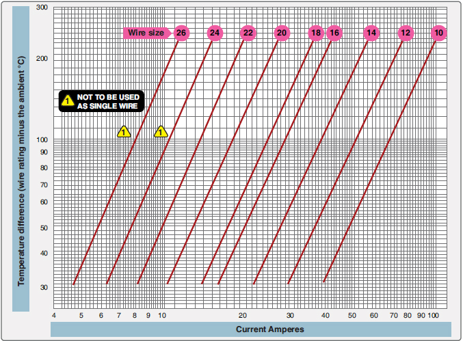
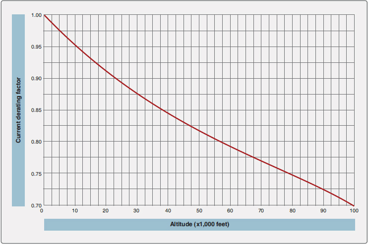
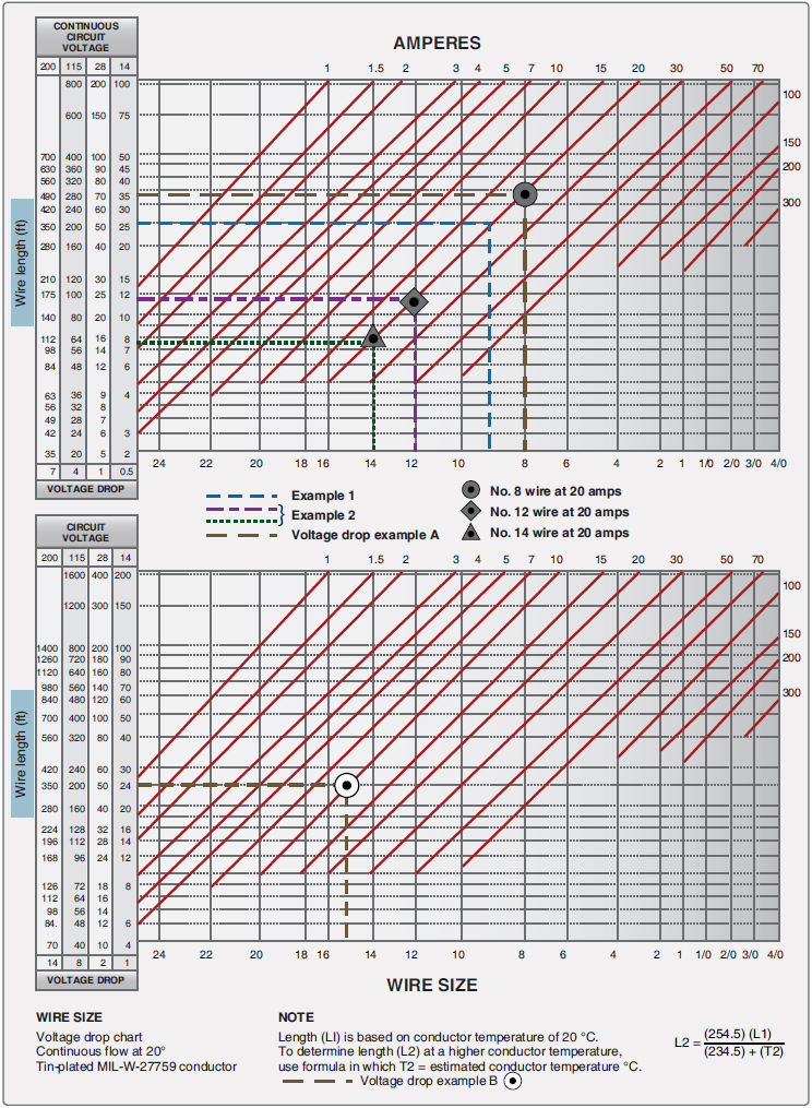
43.13-1B Example
The full document covering many subject matters related to aircraft inspection and repair can be downloaded as a PDF. Click Here
The Aeronautics Guide is another source covering similar subject matter, but with updated graphics such as the figure below. Click Here
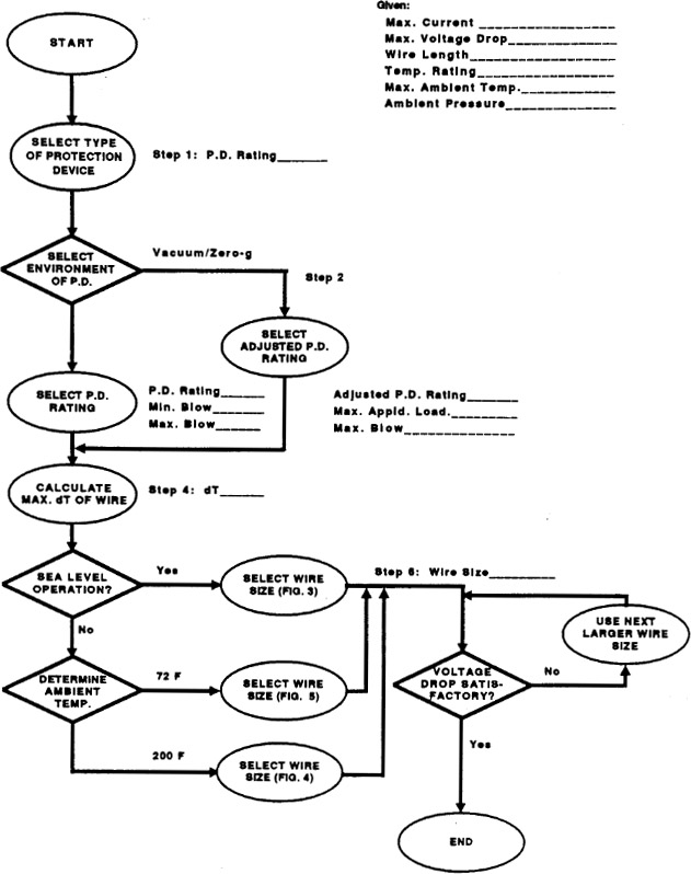
NASA Technical Memorandum 102179 Example
The full document can be downloaded as a PDF. Click Here
Sources:
[1] Society of Automotive Engineers. (Rev. C October 2006, superseded). AS50881 Wiring Aerospace Vehicle. ftp://pklunx.hill.af.mil/data/FA810514R0009_AS50881Rev_C_Wiring_Aerospace_Vehicle.pdf
[2] Federal Aviation Administration. (September 08, 1998). 43.13-1B - Acceptable Methods, Techniques, and Practices - Aircraft Inspection and Repair. Retrieved September 4, 2019, from http://www.faa.gov/documentLibrary/media/Advisory_Circular/AC_43.13-1B_w-chg1.pdf
[3] Aeronautics Guide. Wire Size Selection - Aircraft Electrical System. Retrieved September 4, 2019, from https://www.aircraftsystemstech.com/2017/06/wire-size-selection.html
[4] Federal Aviation Administration. (December 8, 2018). Aircraft EWIS Practices Job Aid 2.0. Retrieved September 4, 2019, from https://www.faa.gov/training_testing/training/air_training_program/job_aids/media/EWIS_job-aid_2.0_Printable.pdf
[5] Air Force Space Command. (June 3, 2009). TECHNICAL REQUIREMENTS FOR WIRING HARNESS, SPACE VEHICLE. Retrieved September 4, 2019, from https://apps.dtic.mil/dtic/tr/fulltext/u2/a633334.pdf
[6] Gaston, Darilyn M., National Aeronautics and Space Administration. (June 01, 1991). Selection of Wires and Circuit Protective Devices for STS Orbiter Vehicle Payload Electrical Circuits. Retrieved September 4, 2019, from https://ntrs.nasa.gov/archive/nasa/casi.ntrs.nasa.gov/19910015188.pdf
[7] Rickman, Steven L., Iannello, Christopher J., National Aeronautics and Space Administration. (September 07, 2016). Heat Transfer Analysis in Wire Bundles for Aerospace Vehicles. Retrieved September 4, 2019, from https://ntrs.nasa.gov/archive/nasa/casi.ntrs.nasa.gov/20160011474.pdf
[8] Rickman, Steven L., Iannello, Christopher J., Shariff, Khadijah, National Aeronautics and Space Administration. (June 09, 2017). Improvements to Wire Bundle Thermal Modeling for Ampacity Determination. Retrieved September 4, 2019, from https://ntrs.nasa.gov/archive/nasa/casi.ntrs.nasa.gov/20170006077.pdf
[9] National Aeronautics and Space Administration. (November 01, 2018). Re-Architecting the NASA Wire Derating Approach for Space Flight Applications. https://ntrs.nasa.gov/archive/nasa/casi.ntrs.nasa.gov/20180007922.pdf
[10] National Aeronautics and Space Administration. (September 01, 1994). New insulation constructions for aerospace wiring applications. https://ntrs.nasa.gov/archive/nasa/casi.ntrs.nasa.gov/19950009641.pdf
[11] National Aeronautics and Space Administration. (September 01, 1994). Kapton wire concerns for aerospace vehicles. https://ntrs.nasa.gov/archive/nasa/casi.ntrs.nasa.gov/19950009630.pdf
Kapton, Tefzel, Teflon are trademarks of DuPont Corporation. Raychem, SPEC 55 are trademarks of the TE Connectivity Ltd. family of companies.
Created: September 4, 2019
Updated: May 15, 2021


